Leg 8 ended in the North Hammock Canyon Reservoir. It will be filled mostly during the 5 hours of peak power generation. During the other 19 hours the fill rate will be very low leading to lowering water levels.
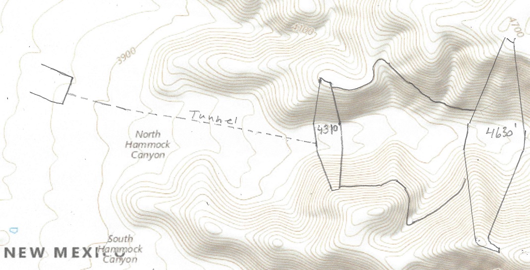
Leg 9 starts with a 1/2 mile wide, 200 ft high reservoir capable of holding 12,000 acre-ft of water. It will be filled during the 5 hours of peak power. The average drop is (4,600 – 4210) = 390 ft and the flow is (12,000 / 5) = 2,400 acre-ft/hr, generating a net power of (390 x 2,400x 0.92) = 861 MW during the 5 peak hours.
From the North Hammock peak power reservoir to the Martin Tank Lake the distance is 59 miles the way the aqueduct takes. It will first descend to 3720 feet before rising to 5190 feet. The descending drop is (4200 – 3720 – 2.2 x 9), an average of 460 feet. The Martin Canyon Lake will top out at 5200 feet with maximum water level at 5190 feet. The total lift of the water in this stage is (5190 – 3720 + 50×2.2) feet = 1580 ft. To lift 21,400 cubic feet per second (1580 x 1.08 – 460 x 0.92) = 1283 feet requires eighteen 100 MW LFTR nuclear reactors. The Martin Tank Lake dam is 22260 feet wide and 230 feet high. It will contain about 30,000 Acre-ft when full, about eighteen hours worth of storage.
What’s in it for New Mexico? The major contribution in this stage is the 861 MW of pumped storage and 2,300 MW of virtual power storage for a total of ( (861 + 2300) x5) = 15.8 GWh per day.
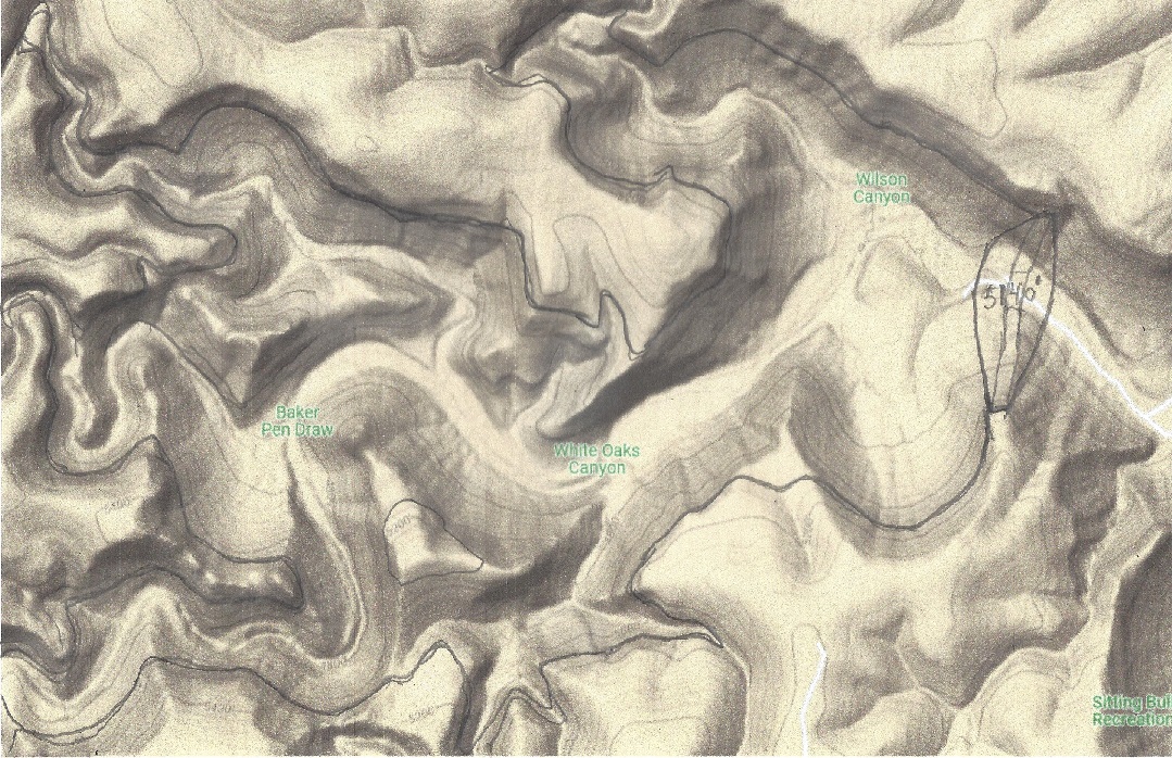
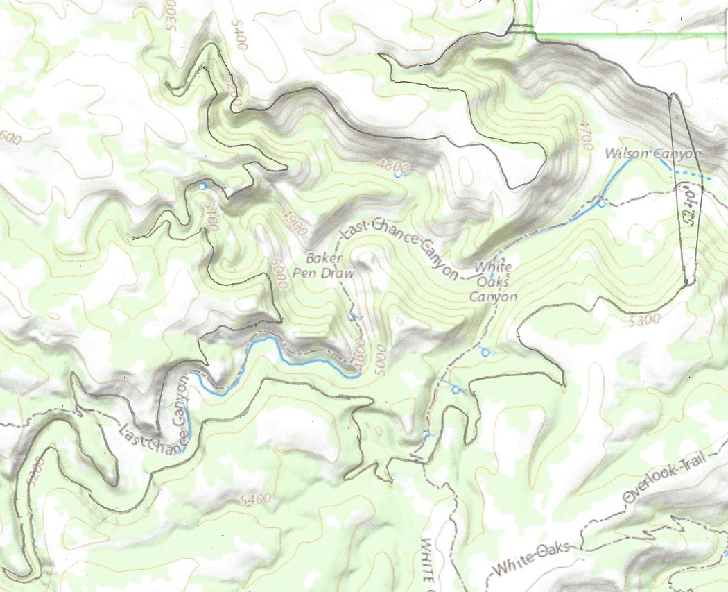
Dam 1 is the White Oaks Canyon Lake. It has a 2000 feet wide and up to 500 feet high dam, topping out at 5,140 feet, and the lake holds a volume of up to 80,000 acre-ft of water.
White Oaks Canyon dam, 500′ high, elevation 5140′
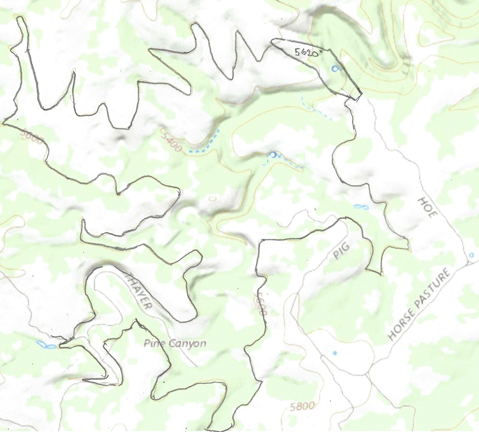
Dam 2 dams the Pine Canyon dam. It has a 2200 feet wide and up to 240 feet high dam, topping out at 5,620 feet, and the lake holds a water volume of up to 60,000 acre-ft. Water is pumped from and released to the White Oaks Canyon lake to the Pine Canyon pumped storage via a 2 mile tunnel.
Leg 8 consists of a tunnel, starting at 4,640 feet and ending at 4140 feet. The 20 mile long tunnel will drop 40 feet as it passes under the mountain. At the 16 mile mark there will be a 460′ vertical drop.
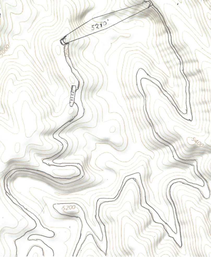
Dam 3 dams the Kingston Canyon lake. It has a 1600 feet wide and up to 250 feet high dam, topping out at 5,210 feet, and the storage holds a volume of up to 25,000 acre-ft of water.
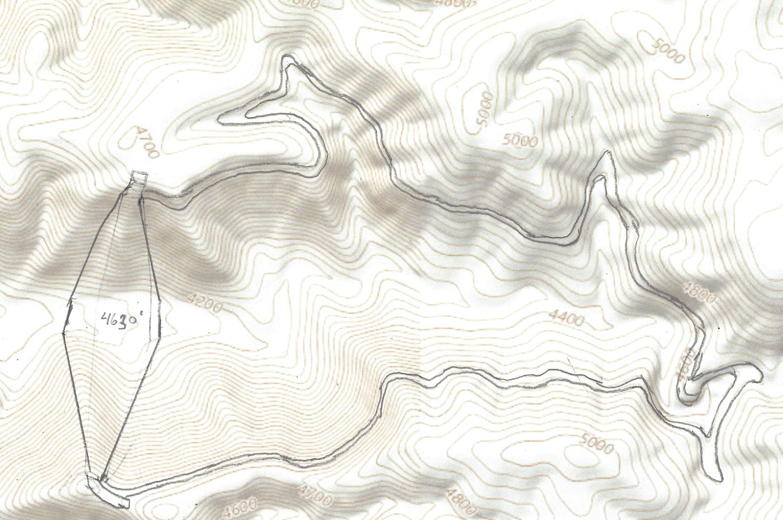
Dam 4 dams the Upper Hammock Canyon Reservoir. It has a 3000 feet wide and up to 500 feet high dam, topping out at 4630 feet, and the lake holds a volume of up to 25,000 acre-ft of water.
Up to now all stages have pumped water uphill. This stage both generates peak power and pumps water. Let us first take the case for pumping water, Stage 1 thru 4.
Stage 1 pumps up to 60,000 acre-ft of water during the 19 off peak hours from an average height of 5,000′ in Dam 1 to an average height of 5,500 in dam 2,a lift of 500′ This requires 1,700 MW of power.
Stage 2, the first 16 miles of the tunnel. The water flow is down to 21,500 cfs , 19 hours a day. During these 19 hours 21,500 cfs flows down the tunnel, the power generated is coming from Dam 1 with a water level of between 4980 feet and 4700 feet with an average of 4940 feet. The tunnel will slope with a 2.2 ft per mile drop.
Stage 3. 16,000 cfs of the water will be pumped up to dam 3, with an average rise from 5,000 feet to between 5200 feet and 4930 feet, (average 5120) for 19 hours, an average lift of 160 feet. This requires a total of 230 MW of power .
Stage 4.The remaining 3,500 cfs of water will be released to dam 4 with an average drop of of 200 feet will generate about 60 MW of power.
Stages 1-4 requires a net power need of 1,570 MW during the 19 off-peak hours.
Stage 5 will release up to 60,000 acre-ft of water from Dam 2 to dam 1 during the 5 peak hours, dropping 500 feet, generating 5,500 WW of power, assuming a 92% generating efficiency.
Stage 6 will release up to 25,000 acre-ft of water from dam 3 to dam 4 during the 5 peak hours, dropping an average 600feet, generating 2.700 MW of power.
What’s in it for New Mexico? This leg is very important, since it will provide up to 41 GWh daily of pumped storage electricity to the national grid, and so make it possible to stabilize the net when more solar panels are installed. The 1,570 MW of power needed for this leg will hopefully come mostly from solar and wind power
Leg 7 of the Transcontinental aqueduct is 90 mils in Texas, rising from 2800′ to 3640′. From there it flows 115 miles in New Mexico rising to 5200′.
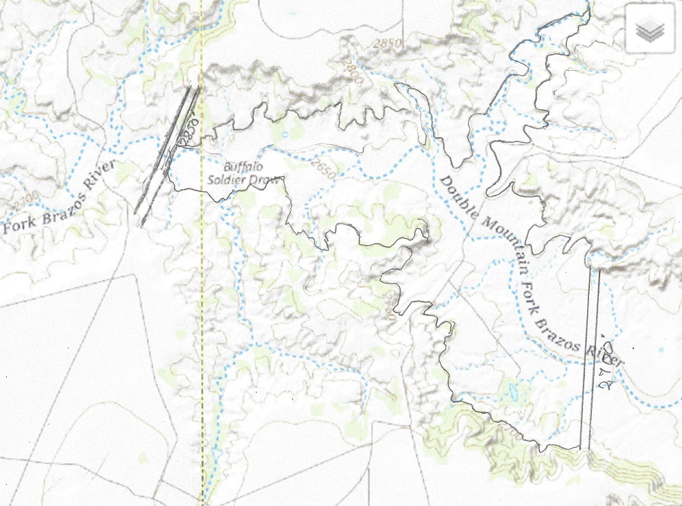
The upper dam of Soldier Mountain Draw, capacity 40,000 acre-ft.
The elevation at the buffalo Soldier Draw dam will top out at 2,850 feet with maximum water level at 2,830 feet. The White Oaks Canyon dam is 560 feet high and will top out at 5,240 feet with an average water level at 5,000 feet. The total lift of the water in stage 5 is (5,000 – 2,800 + 205×2) feet = 2610 ft. To lift 21,600 cubic feet per second 2610 feet requires fifty 100 MW LFTR nuclear reactors, twenty on the Texas Grid and thirty on the Western national grid. The White Oaks Canyon Lake will contain about 130,000 Acre-ft of water when full, about three days of storage. For 5 hours per day these fifty reactors used in this stage can provide 5.0 GW of peak power to the grid instead of pumping water, thus acting as a virtual hydroelectric peak power storage. 2 GW of this will be used by the Texas Power Grid, and 3 GW by the Western U.S. Power grid, and they have to be coordinated.The White Oaks dam will look like this:
What’s in it for Texas? Wind power is already 22% of the source for the Texas power grid, but Texas has up to now no pumped water storage, and until this is fixed coal and natural gas backup must be provided when the wind doesn’t blow. This leg will provide 2 GW of virtual hydro-power generation to the Texas power grid by not pumping water for up to 5 hours and thus provide 10 GWh of peak power daily. This will greatly help stabilize the Texas power grid, and facilitate the phasing out of coal power and help the transition to electric vehicles, which will add stress to the stability of the grid by their uneven recharging patterns.
What’s in it for New Mexico? This leg will provide 3 GW of virtual hydro-power generation by not pumping water for up to 5 hours and thus provide 15 GWh of peak power daily.
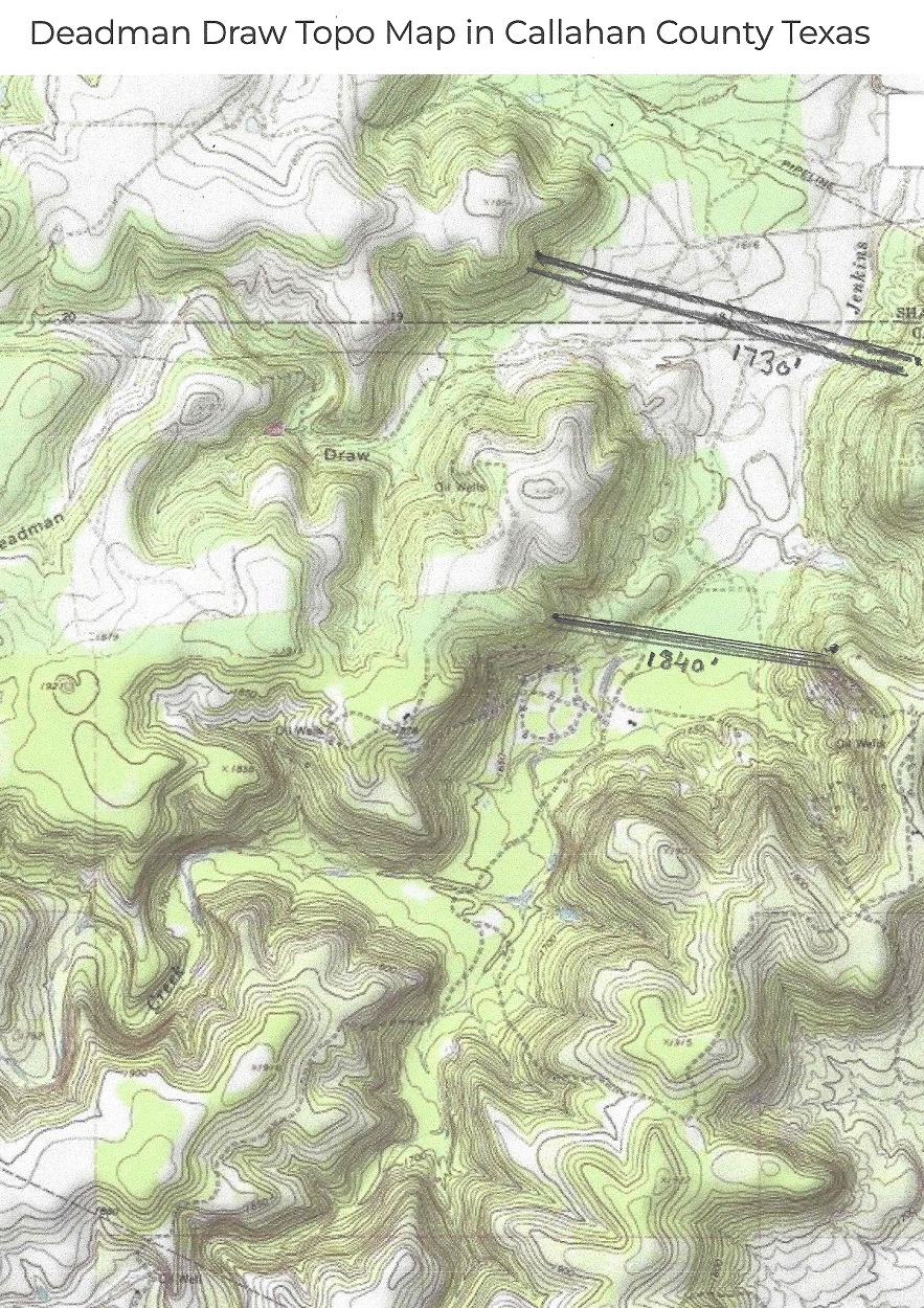
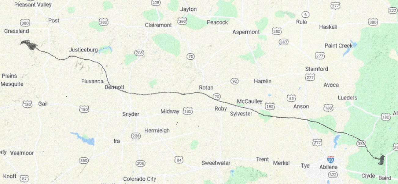
This leg has the freedom to pump water at 21,800 cfs or less, including stopping for up to 5 hrs/day to provide virtual peak hydro-power for the Texas grid. This must be coordinated with leg 5 and leg 7. Total distance of the aqueduct is 135 miles, from elevation 1830′ to elevation to 2840′.
From Deadman Draw dam to Buffalo Soldier Draw dam, a distance of 135 miles.
The water elevation at Deadman Draw dam is nominally 1,830 feet. The Buffalo Soldier Draw dam yet to be built will top out at 2,850 feet with maximum water level at 2,840 feet. The total lift of the water in stage 3 is (2,840 – 1,830 + 135×2) feet = 1,280 ft. To lift 21,800 cubic feet per second 1,280 feet requires twenty-five 100 MW LFTR nuclear reactors The upper reservoir will contain about 40,000 Acre-ft when full, about one day worth of storage. For 5 hours per day these twenty-five 100 MW reactors can provide 2.5 GW of peak power to the grid.
There will be a lower dam to provide hydroelectric power storage of 4.5 GWh, or 900 MW for 5 hours. After each use the lower dam will be re-emptied by pumping back the water to the upper dam, using 5.4 GWh of power, hopefully using surplus wind or solar power.
The aqueduct will go thru and dug sown at 1590’elevation
What’s in it for Texas? Wind power is already 22% of the source for the Texas power grid, but Texas has up to now no pumped water storage, and until this is fixed coal and natural gas backup must be provided when the wind doesn’t blow. This leg will provide 4.5 GWh of peak power per day from the pumped water storage. In addition the 2.3 GW of Nuclear power can provide virtual hydro-power generation by not pumping water for up to 5 hours and thus provide 6 GWh of peak power daily. This will greatly help stabilize the Texas power grid, and facilitate the phasing out of coal power and help the transition to electric vehicles, which will add stress to the stability of the grid by their uneven recharging patterns. I addition, the City of Lubbock can purchase water from the aqueduct, to be negotiated.
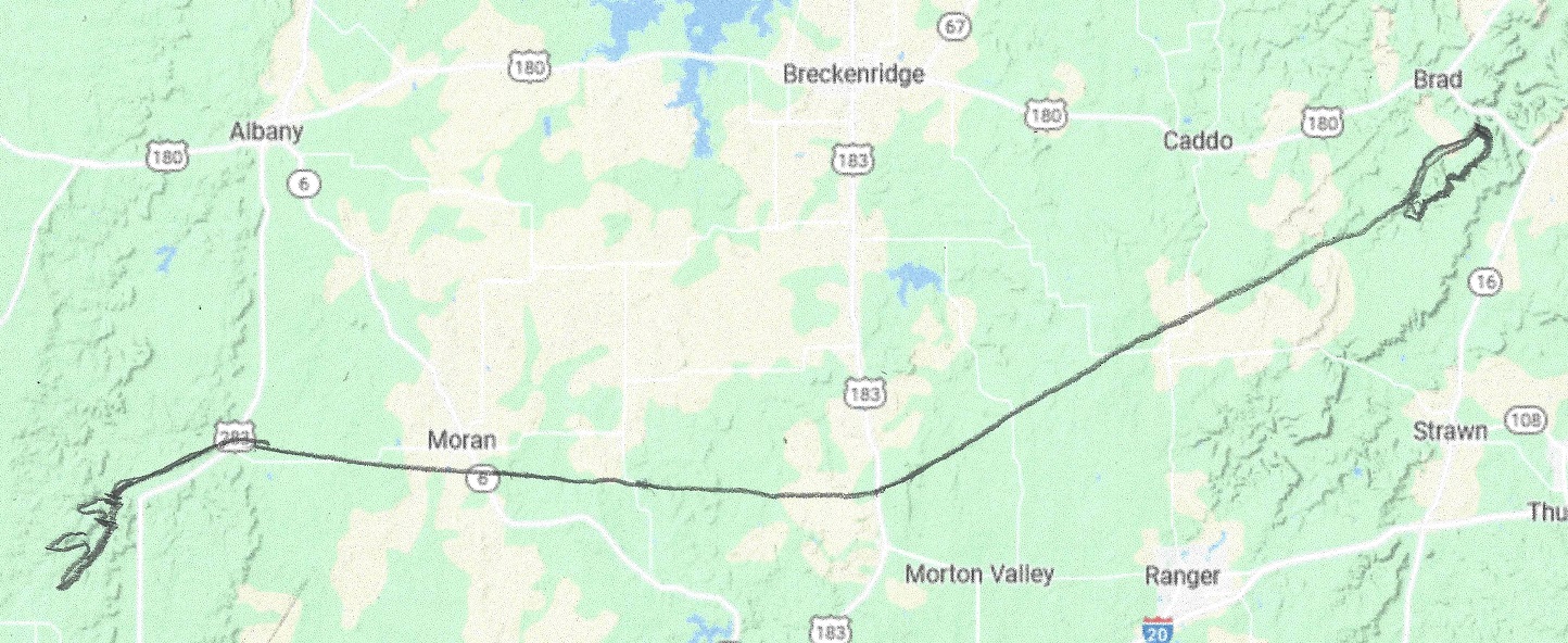
The distance of leg 5 is 10 miles of water and 60 miles of aqueduct. This leg has the freedom to pump water at 22,000 cfs or less, including stopping for up to 5 hrs/day to provide virtual peak hydro-power for the Texas grid.
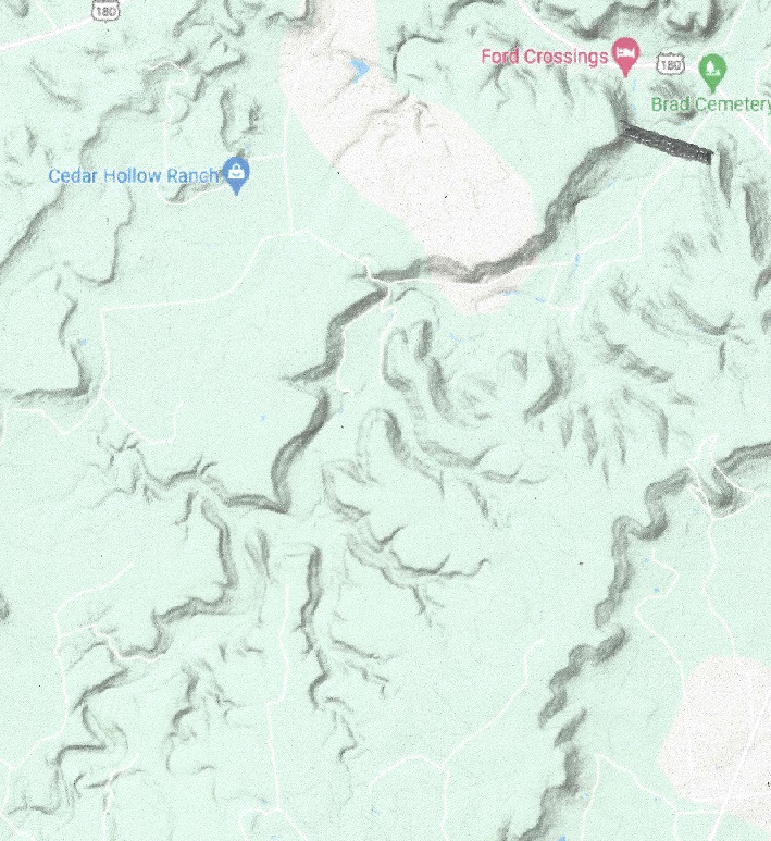
The elevation at Brad reservoir is nominally 1260 feet. From 25 miles East of Breckenridge the aqueduct goes W to 19.5 miles ENE of Abilene, a distance of 60 miles . The dam yet to be built will top out at 1840 feet with maximum water level at 1830 feet. The total lift of the water in stage 3 is (1830 – 1260 + 60×2) feet = 690 ft. To lift 22,000 cubic feet per second 690 feet requires twelve 100 MW LFTR nuclear reactors The upper Baird reservoir will contain about 90,000 Acre-ft when full, about two days worth of storage. For 5 hours per day these twelve 100 MW reactors can provide 1.2 GW of peak power to the grid. There will be a lower dam to provide hydroelectric power storage of 4 GWh, or 800 MW for 5 hours. After each use the lower dam will be re-emptied by pumping back the water to the upper dam, using 4.75 GWh of power, hopefully using surplus wind or solar power.
b
What’s in it for Texas? Wind power is already 22% of the source for the Texas power grid, but Texas has up to now no pumped water storage, and until this is fixed coal and natural gas backup must be provided when the wind doesn’t blow. This leg will provide 4 GWh of peak power per day from the pumped water storage. In addition the 1.2 GW of Nuclear power can provide virtual hydro-power generation by not pumping water for up to 5 hours and thus provide 6 GWh of peak power daily. This will greatly help stabilize the Texas power grid, and facilitate the phasing out of coal power and help the transition to electric vehicles, which will add stress to the stability of the grid by their uneven recharging patterns.
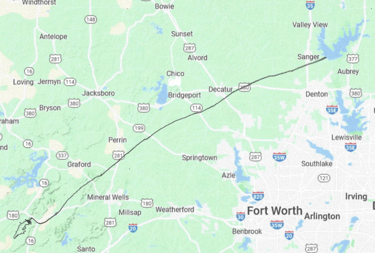
Leg 4 of the Transcontinental aqueduct is 15 miles of lake and 100 miles of aqueduct.
Lake Ray Roberts, elevation 625′, must be kept nearly constant.
The elevation at Lake Ray Roberts is 625 feet. From here the aqueduct goes WSW to the Brad dam. It crosses the Brazos river, but does not interfere with it. (This can change if desired). The Brad dam is located just south of the Brad Cemetery on U.S. route 180, 25 miles East of Breckenridge. The dam, yet to be built will top out at 1280 feet with maximum water level at 1270 feet. The total lift of the water in stage 2 is (1,260 – 625 + 100×2) feet = 835 ft. To lift 22,000 cubic feet per second 835 feet requires seventeen 100 MW LFTR nuclear reactors. Lake Brad will contain about 60,000 Acre-ft when full, about one and a half day’s worth of storage. For 5 hours per day these 17 reactors can provide 1.7 GW of peak power to the grid. (The power can also partly be provided by wind power, during which time the LFTR’s can make hydrogen for extra peak power storage).
What’s in it for Texas? The 1.7 GW of Nuclear power can provide virtual hydro-power generation by not pumping water for up to 5 hours and thus provide 8.5 GWh of peak power daily. This has to be done in conjunction with Leg 3.
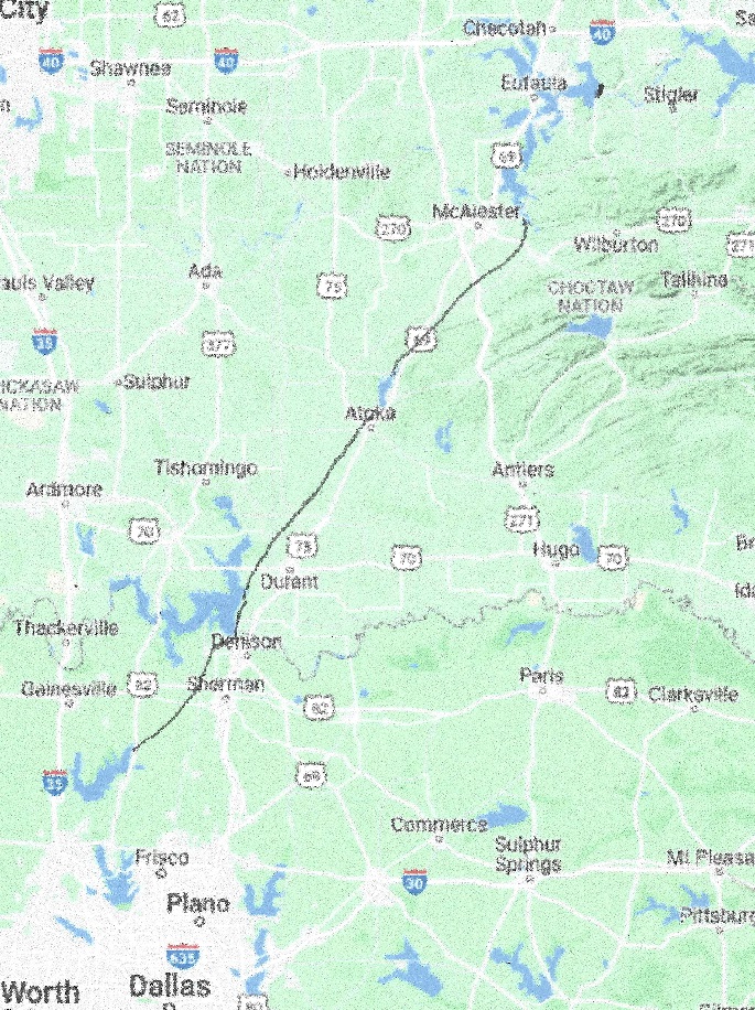
Stage 3 consists of 40 miles on Lake Eufaula, 10 miles on Aquila lake and 125 miles of a 22,000 cfs aqueduct, 95 miles in Oklahoma and 30 miles in Texas. This segment should ideally have used lake Texoma, but the water in it is brackish with between one half to one percent salinity, so it is unusable for drinking water, and even for agricultural purposes.
It starts out at lake Eufaula:
Conservation pool elevation 585′
From there the real aqueduct will start, unencumbered by barge traffic regulation. It will go from the southern tip of Lake Eufaula to lake Atoka, a distance of 40 miles. Lake Atoka is 10 miles long.
Lake Atoka elevation is 590′
Then from Lake Atoka it will pass by lake Texoma on ther downslope of thee Denison dam at an elevation of 640′. From there it will go to Lake Ray Roberts
Leg 3 total length 50miles lake, 125 miles aqueduct, end point Lake Ray Roberts, elevation 625′
The elevation at lake Atoka is about 590′. The aqueduct will have a capacity of 22,000 cfs, and it will climb from Eufaula to about 740′ before going down again to lake Atoka. From lake Atoka it will only pump up water for 85 miles. The aqueduct water level drops by 2′ per mile. Total pumping up will be 365′ and going down water release will be 110′ The total power need for this stage will be up to 665 MW assuming 92% pumping and generation efficiency. three 200 MW LFTR SMR will take care of the power needs this stage, and can be used for peak power generation when pumping is temporarily shut off. It is important to keep the water level steady at Lake Ray Roberts.
What’s in it for Oklahoma? Eufaula lake flood control will be greatly enhanced. Lake Atoka flood control will be enhanced and in case of drought extra water will be supplied to keep lake levels steady. There will be about 200 MW virtual hydro-power energy provided for up to 5 hours/day to stabilize the grid with peak power.
What’s in it for Texas? In case of drought Lake Ray Roberts can supply extra water to the Dallas area. The water levels will be stabilized at Lake Ray Roberts. There will be about 400 MW virtual hydro-power energy provided for up to 5 hours/day to stabilize the Texas grid with peak power.
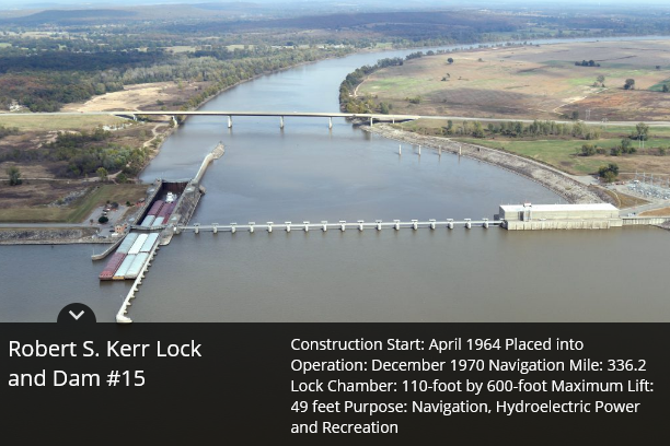
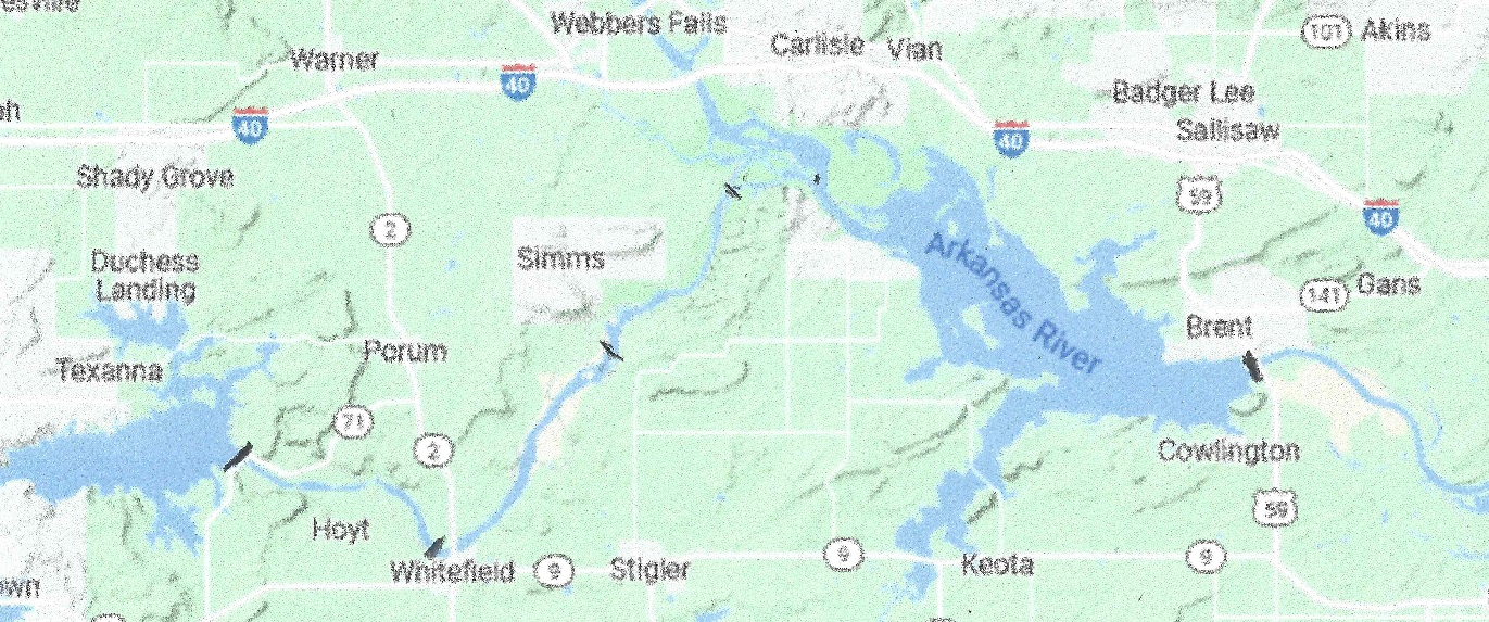
The length of Leg 2 is 20 miles on the Robert S Kerr reservoir and 22 miles on the Canadian river.
Elevation 458′
The Robert S Kerr reservoir has an area of 43,000 acres and its elevation is regulated by the McClellan-Kerr Arkansas River Navigation System. This means that the water can be pumped up or released as long as it is coordinated for the whole canal system. This also means that the water flow can be stopped and the power normally used to pump up water can be used as peak power, which can come in handy on a hot humid day with no sun and no wind and every air conditioner in the area is going full blast to take out the oppressive humidity.
The part of the aqueduct going up the Canadian river will have 3 20 ft dams with concrete spillways, each with a 20,000 cfs reversible flow pumping station. The map:
The dam will have a 20,000 cfs pumping station added lifting water 87 ft.
The Eufaula Dam. The Eufaula dam Riverbed at 498′ conservation pool at 585′
The total power consumption in this stage will be up to 265 MW. The preferred power plant will be 3 100 MW LFTR SMRs.
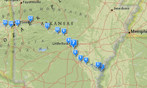
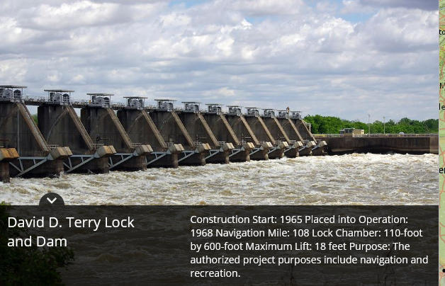
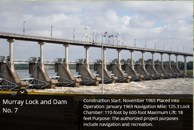
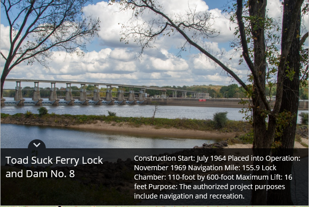
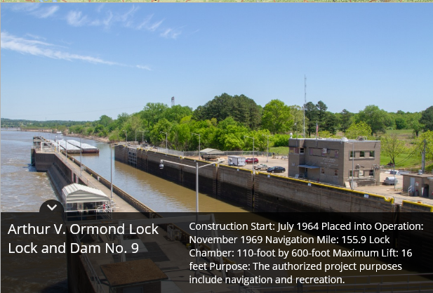
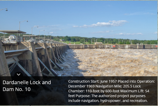
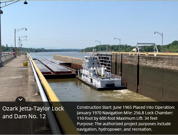
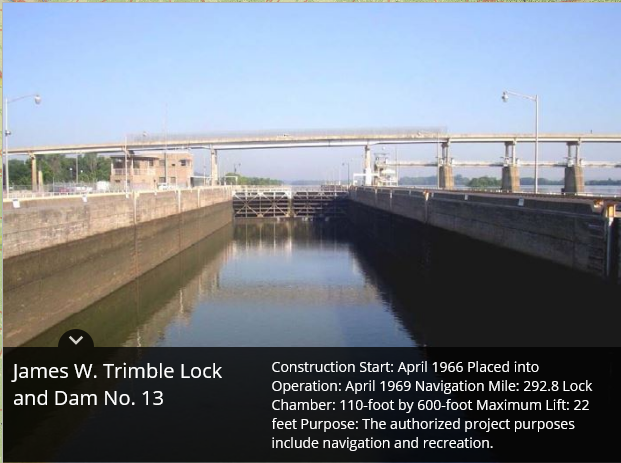
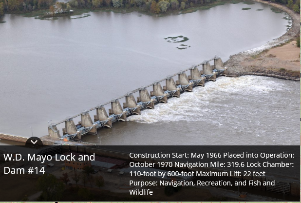
The Trans-Continental aqueduct starts out at the Mississippi river, and for the first leg follows the Arkansas River from Mississippi River to Lock15 of the Arkansas River, a distance of 319 miles.
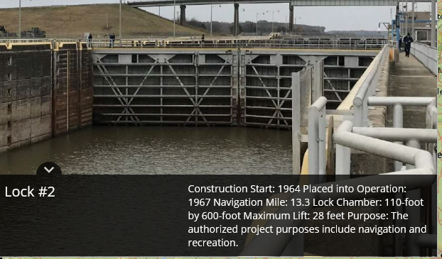
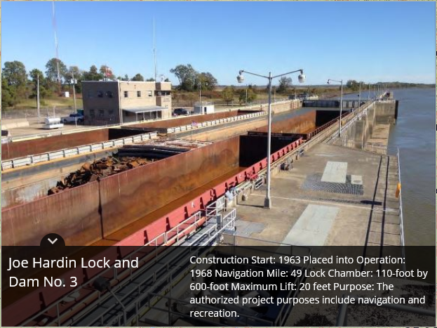
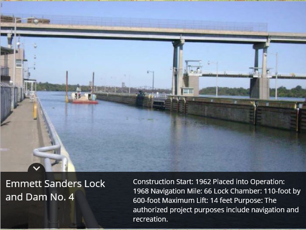
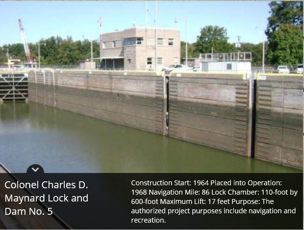
Location of the locks and pumping stations on the Arkansas river.
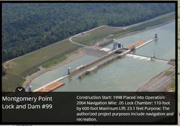
Lock 1, entrance from the Mississippi River to the White river. The water surface at Montgomery Point has fluctuated from elevation 104′ to 172′.
This lock was added later to better accommodate barge traffic when the Mississippi River was running abnormally low. If the Mississippi is normal to high level, this lock is bypassed. Since we are going to move 23,200 cfs of water over the rocky mountain the flow amount in Arkansas river will be reduced by the same amount. In times of drought, the Arkansas River flow is most often less than 23,200 cfs. To alleviate that, a series of 20,000 cfs pumps will be installed, one in every lock of the canal, beginning with Lock 3.
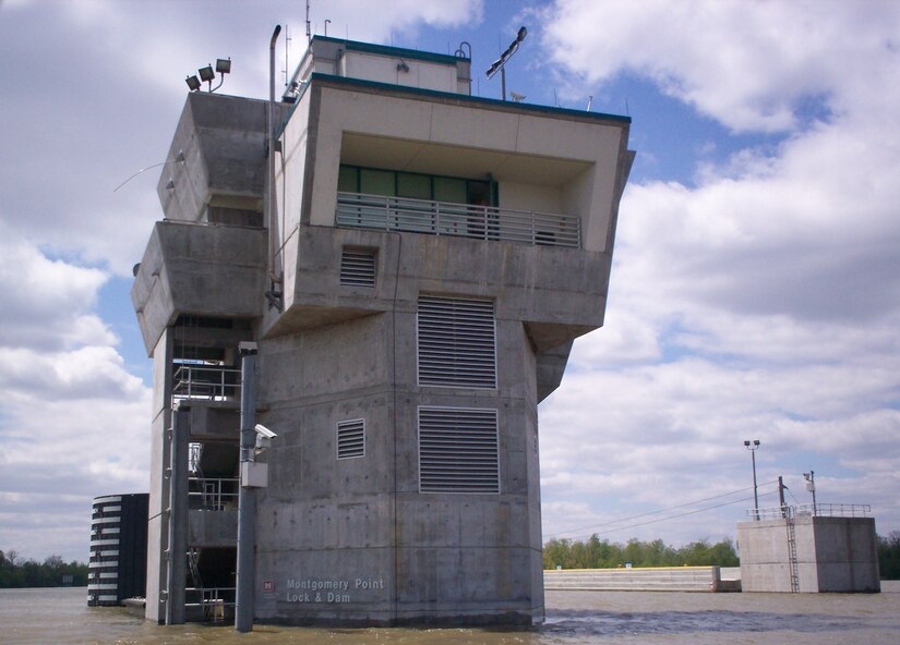
Montgomery Point Lock and Dam features “first of its kind” hydraulically operated gates. When the tail water is at elevation 115′ and rising, the dam gates are flat on the bottom of the river and barge traffic passes over the gates in the navigation pass spillway to minimize lockages saving time and money.This lock is frequently submerged. Only the top of the control tower remains above water
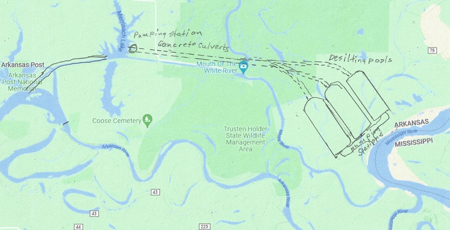
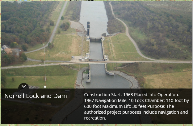
The Mississippi river is muddy. When water is pumped up there needs to be a number of de-silting pools, where the silt is returned to the Mississippi river. Here is suggested 3 pools, each capable of de-silting 10,000 cfs of water, one for the Trans-Rocky Mountain aqueduct, and two for the Trans-Continental aqueduct, being built as the whole aqueduct is nearing completion. The top of the pools is set at 150 ft elevation. Should the Missisippi River flood higher than 142 feet the operation will be shut down until elevation is below 142 feet again, and Lock 2, the Norrell Lock and dam is operational again. For the Trans-Continental aqueduct up to 20,000 cfs needs to be pumped up between 20 and 62 feet, for an energy consumption of between 1MW and 112 MW. The map below show one possible location for the pools:
The de-silting pools.Elevation 142′ No changeElevation 162′ No changeElevation 182′Elevation 1196′Elevation 213′Elevation 231′Elevation 249Elevation 265′Elevation 284′Elevation 336′Elevation 370′Elevation 391′Elevation 412′Elevation 458′
From Lock # 3 to lock # 15 (12 locks # 11 is missing) the Power houses have to either replace two of the operating turbines to a corresponding dual function pump/generator, or add a 20,000 cfs pump.
By removing 20,00 cfs from the flow of water in the Arkansas river, it will be necessary to add these pumps to ensure functioning locks even in times of extreme droughts. The total power generated by the power stations will be reduced by 20,000 cfs times (458 – 127) feet * 0.9 or about 630 megawatts total. This is most of the time all the power that was generated, so the standard hydropower generation in the Arkansas river will be for all practical purposes eliminated.
As a side note, every lock opening uses up water equivalent of between 22 and 66 kWh depending on the size of the lift or lowering of the barges. This is constant and not dependent on the size of the barges or boats. When the spillways are in use, the water is “free”, but otherwise every lock opening costs a few dollars in energy, not much, but in case of a drought the fact that water is pumped back up the river will help increase the capacity.
What is in it for Arkansas? The added pumps will give an additional tool to control the canal system. In addition, in the case of floods it will somewhat alleviate the flood control, and serve the canal system better in times of drought. To add 630 megawatts to the system, may I suggest 3 200 MW LFTR nuclear reactors, they are carbon neutral. In addition they have the ability to shut off the pumping of water and let the power plants provide 600 MW virtual hydro-storage power for up to five hours/day. The barges will benefit from sometimes go with the flow, and sometimes travel over still water, shortening the time of transport substantially.
The power companies in California asked people to avoid charging their electric vehicles to lessen the strain on the power grid.
California has a giant power problem. It depends on solar power to over 10% and wind power to 10%, but depends on hydro power for over 13% of their needs. The two last nuclear power plants in Diablo Canyon, supplying 9% of Californians electricity are being shut down in 2024 and 2025. Hydro-power is declining because of the drought, so the rest has to be made up by fossil fuels and imports from other states. Therefore California has one of the largest transmissions losses of any state, close to 10%. When the wind doesn’t blow and the sun doesn’t shine they import peak power at a price that has a few times been as high as one dollar per kWh. But they are building fast charging stations for their electric vehicles:
This one is in Menlo Park, Ca. Where Else?
The infrastructure bill will add $7.5B in EV charging stations, which could result in around 1,900 highway and rural stations, 100,000 urban stations, and 215,000 Level 2 stations for workplaces, apartments, and airports. There are already 45,000 private charging stations, and s number of exclusive Tesla charging stations. And then there is no saying how many are installing a fast charger in their garage. If electric cars really takes off we will have to greatly expand our electric grid, which is still powered over half with fossil fuels.
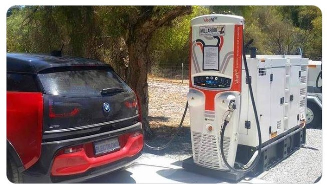
But fear not, when all else fails, here is a diesel powered electric charging station for your electric vehicle:
Should you run out of charge there is always AAA:
I am for electric vehicles as soon as the electric grid is fixed up, the dependency of fossil fuel to stabilize the grid and the grid is built up to accommodate electric vehicles being charged at the same time. As it is now, over half of all electricity is still produced using fossil fuels, and coupled with 10% transmission losses and conversion losses, plus that electric vehicles use electricity to get heated, they are not carbon neutral.
I have a proposal to solve the water problems in the American Southwest and at the same time triple the nation’s hydro-power storage capacity allowing for a greater use of solar panels, and some windmills, they will be a small part of the solution, but the great change will be the use of Small Modular Reactors, preferably Liquid Fluoride Thorium Reactors. The proposal is here-.