The Trans-Continental aqueduct starts out at the Mississippi river, and for the first leg follows the Arkansas River from Mississippi River to Lock15 of the Arkansas River, a distance of 319 miles.
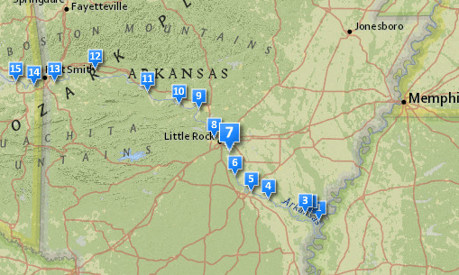
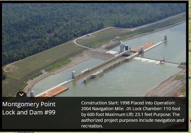
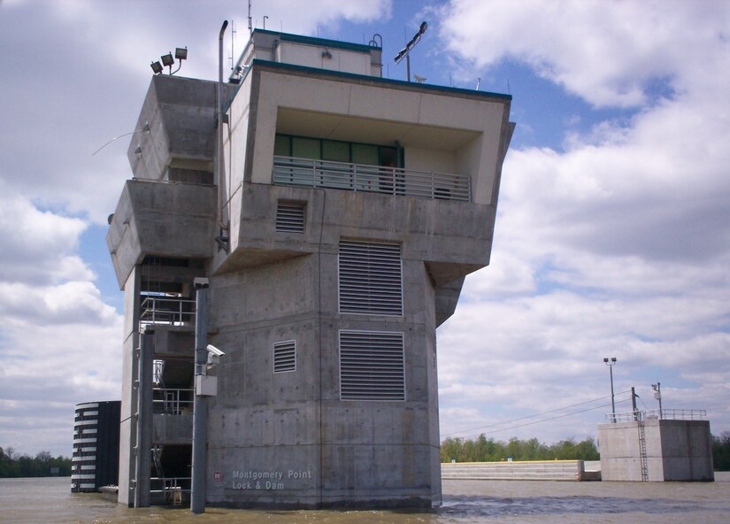
Lock 1, entrance from the Mississippi River to the White river. The water surface at Montgomery Point has fluctuated from elevation 104′ to 172′.
This lock was added later to better accommodate barge traffic when the Mississippi River was running abnormally low. If the Mississippi is normal to high level, this lock is bypassed. Since we are going to move 23,200 cfs of water over the rocky mountain the flow amount in Arkansas river will be reduced by the same amount. In times of drought, the Arkansas River flow is most often less than 23,200 cfs. To alleviate that, a series of 20,000 cfs pumps will be installed, one in every lock of the canal, beginning with Lock 3.
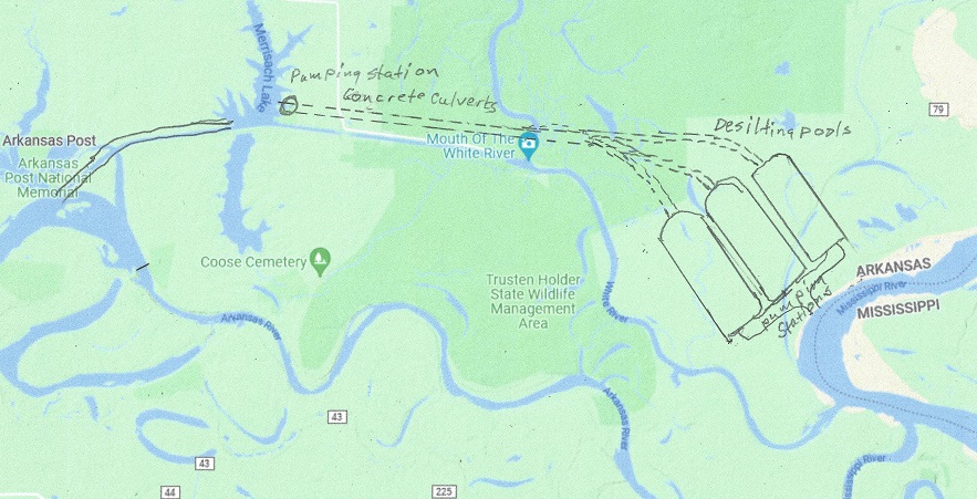
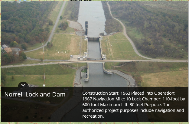
The Mississippi river is muddy. When water is pumped up there needs to be a number of de-silting pools, where the silt is returned to the Mississippi river. Here is suggested 3 pools, each capable of de-silting 10,000 cfs of water, one for the Trans-Rocky Mountain aqueduct, and two for the Trans-Continental aqueduct, being built as the whole aqueduct is nearing completion. The top of the pools is set at 150 ft elevation. Should the Missisippi River flood higher than 142 feet the operation will be shut down until elevation is below 142 feet again, and Lock 2, the Norrell Lock and dam is operational again. For the Trans-Continental aqueduct up to 20,000 cfs needs to be pumped up between 20 and 62 feet, for an energy consumption of between 1MW and 112 MW. The map below show one possible location for the pools:
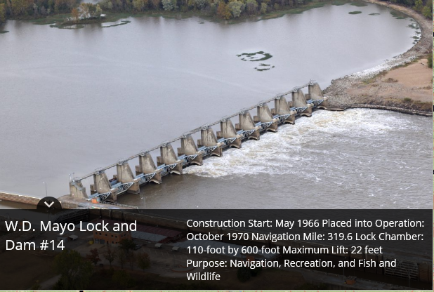
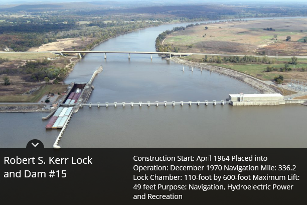
From Lock # 3 to lock # 15 (12 locks # 11 is missing) the Power houses have to either replace two of the operating turbines to a corresponding dual function pump/generator, or add a 20,000 cfs pump.
By removing 20,00 cfs from the flow of water in the Arkansas river, it will be necessary to add these pumps to ensure functioning locks even in times of extreme droughts. The total power generated by the power stations will be reduced by 20,000 cfs times (458 – 127) feet * 0.9 or about 630 megawatts total. This is most of the time all the power that was generated, so the standard hydropower generation in the Arkansas river will be for all practical purposes eliminated.
As a side note, every lock opening uses up water equivalent of between 22 and 66 kWh depending on the size of the lift or lowering of the barges. This is constant and not dependent on the size of the barges or boats. When the spillways are in use, the water is “free”, but otherwise every lock opening costs a few dollars in energy, not much, but in case of a drought the fact that water is pumped back up the river will help increase the capacity.
What is in it for Arkansas? The added pumps will give an additional tool to control the canal system. In addition, in the case of floods it will somewhat alleviate the flood control, and serve the canal system better in times of drought. To add 630 megawatts to the system, may I suggest 3 200 MW LFTR nuclear reactors, they are carbon neutral. In addition they have the ability to shut off the pumping of water and let the power plants provide 600 MW virtual hydro-storage power for up to five hours/day. The barges will benefit from sometimes go with the flow, and sometimes travel over still water, shortening the time of transport substantially.
